VAXBI Sync Comm
Technical Schematics
Order Number: T1042-0-1
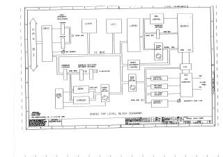
This document provides a detailed set of circuit diagrams for the DSB32 VAXBI Synchronous Communications module. It covers the following subsystems: - BI Interface: Logic for communicating with the VAXBI bus. - Microprocessor and Interrupt Subsystem: The uVAX processor and VIC interrupt control logic. - Memory Subsystem: RAM and ROM modules. - Communications Subsystem: DUSCC controller logic, X.21 interface circuitry, and data transmission/reception buffers. - Control and Diagnostic Registers: LED and diagnostic register configuration. - Power and Backplane: Power distribution, capacitors, and backplane pin signals.
Site structure and layout ©2026 Majenko Technologies