Data Buffer and Status
Data Buffer Control
Order Number: DICS-M7104-0-1
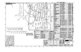
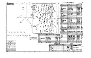
This document contains a set of engineering schematics detailing the Data Buffer and Status circuitry, likely for a PDP-11 series system (RK8-E). The drawings cover:
- IC Pin Locations: A layout of integrated circuits on the board.
- Parts List: A comprehensive list of electronic components used on the board.
- Circuit Schematics: Detailed logic diagrams for the data buffer control and data buffer functions, including various gate-level implementations of control logic and data routing.
Site structure and layout ©2026 Majenko Technologies