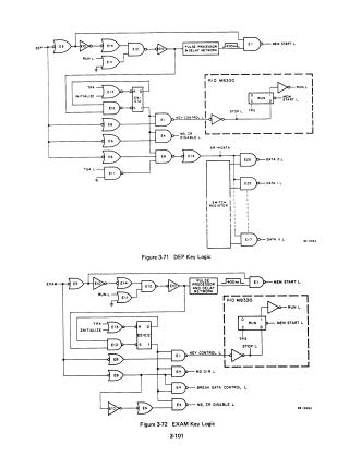
DEP, EXAM, CONT, CLEAR, and SING STEP/HALT Switch Logic
Maintenance Guide
Order Number: 3-101-3-105
This document provides detailed logic diagrams and functional explanations for computer front panel control circuits. It covers:
- Key Logic: Detailed schematics for DEP (Deposit), EXAM (Examine), CONT (Continue), and CLEAR keys, along with SING STEP and HALT switch logic.
- Display Logic: An explanation of the display circuit (Figure 3-76), including the operation of indicator lamps for EMA, MEMORY ADDRESS, and the RUN status. It describes how voltage thresholds and transistor switching are used to distinguish between bright and dim states to extend lamp life.
- Control Signals: Logic diagrams for data bus display control and selection circuits, showing how the Function Selector Switch enables different data paths (MD, DATA, or STATUS) for front panel visualization.
Site structure and layout ©2026 Majenko Technologies