10-2 Input NAND Gates M113
Order Number: M113-0-1
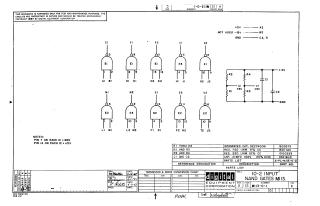
This document is a technical schematic diagram for the M113 module, which contains 10 two-input NAND gates. It includes the circuit layout, pin configurations (Pin 7 for GND, Pin 14 for +5V), a parts list specifying integrated circuits (DEC7400N), resistors, and capacitors, as well as reference designations.
Related Documents
| 10-2 Input NAND Gates MI13 | MII3-0-1 |
Site structure and layout ©2026 Majenko Technologies