Six Flip-Flops
Order Number: M216-0-1
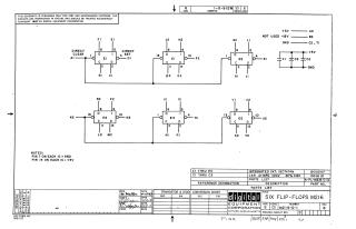
This document contains the official schematic diagram for the M216 Six Flip-Flops module, dated 1967. It provides the necessary circuit logic, including the arrangement of integrated circuits (DEC7474N) and capacitor connections required for test and maintenance purposes. The schematic also specifies that pin 7 on each integrated circuit is connected to ground (GND) and pin 14 is connected to +5V.
Related Documents
| Six Flip-Flops | M216-0-I |
Site structure and layout ©2026 Majenko Technologies