Teletype Testing with PDP-1
Order Number: PDP-1-TT
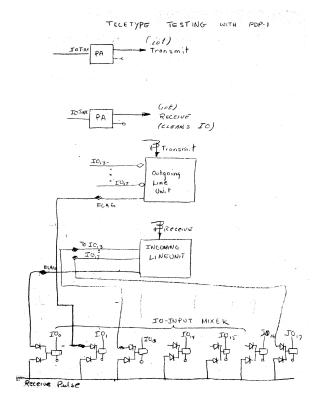
This document contains a series of technical logic and wiring diagrams related to Teletype testing on a PDP-1 computer system. The schematics detail:
- Teletype Operations: The transmit and receive logic flow, including IOT commands, outgoing and incoming line unit structures, and an I/O input mixer.
- System Timing: Diagrams showing common timing for transmit and receive functions, and a dedicated common clock circuit for receiver operations.
- Buffer and Control: A detailed view of a single buffer receiver (incoming line unit) using a character-based timing logic (CTR0, CTR1, CTR2) and shift registers.
- Local Transmit Logic: Schematics for the local transmit Teletype (TT) unit, including connections for flags, common start signals, and buffer interfaces.
Site structure and layout ©2026 Majenko Technologies