Minnow ALU Data Paths
Order Number: 8-DD-M8626-0
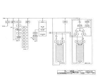
This document contains a series of schematic diagrams for the Minnow Arithmetic Logic Unit (ALU), detailing the data paths and control signals. The diagrams illustrate the organization of the 2901 bit slices, pipeline registers, status controllers, and various buffer and control signals. It covers the ALU structure across several pages, showing the interconnection of the ALU, registers, and memory components.
Site structure and layout ©2026 Majenko Technologies