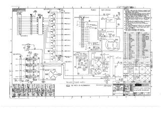
Power and Control Schematic Diagram
Schematic Diagram
8L, 8E, 8M, 8F
Order Number: PC04-0-2
This document contains detailed schematic diagrams for the power and control systems of the PC04 paper tape reader/punch. It includes wiring tables, component lists, and notes regarding assembly configurations and modifications. Key sections detail power supply connections, punch/reader logic, and regulator board layouts for various models including BB, BC, RB, BL, BM, PL, and PV.
Site structure and layout ©2026 Majenko Technologies