Time State Generator
Order Number: M775-0-1
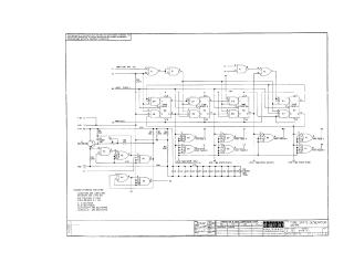
This document is a technical schematic diagram for the Digital Equipment Corporation M775 Time State Generator module. It illustrates the logic circuit design, including NAND gates (E1-E11) and J-K flip-flops used for timing state generation. The schematic includes voltage requirements (+3V and +5V), reference components, and a transistor/diode conversion chart, intended for test and maintenance purposes.
Site structure and layout ©2026 Majenko Technologies