Terminator
Order Number: G737-0-1
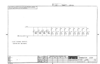
This document provides the electrical schematic for the G737 Terminator board from Digital Equipment Corporation, dated 1970. The circuit includes multiple capacitors (C1-C4) and a bank of resistors (R1-R18) configured for termination purposes. It also includes a transistor and diode conversion chart template.
Site structure and layout ©2026 Majenko Technologies