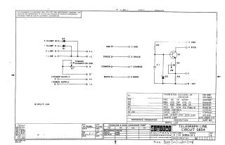
Telegraph Line Circuit
Order Number: CS-G854-0-1
This document provides a schematic diagram for the Telegraph Line Circuit, identified as circuit G854. It was designed by Digital Equipment Corporation in 1967 for test and maintenance purposes. The schematic outlines the electrical connections, including clamps, power supply lines, ground and signal indicators (Space, Common, Mark), and a transistor-based converter circuit. The document includes a parts list specifying component values and part numbers for transistors, resistors, diodes, and capacitors, as well as a transistor and diode conversion chart.
Site structure and layout ©2026 Majenko Technologies