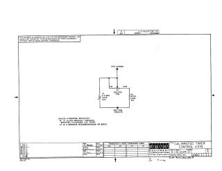
Calibrated Timer Control K374
Order Number: K374-0-1
This single-page document provides the schematic diagram for the K374 Calibrated Timer Control, dated 1967. It details the electrical connections for a circuit involving a potentiometer (R1), a capacitor (C1), and a resistor (R2). It also includes notes on specific component manufacturer models (Allen-Bradley and Sprague) and their equivalents.
Site structure and layout ©2026 Majenko Technologies