Filtered Differential Amplifier
G590
Order Number: G590-0-1
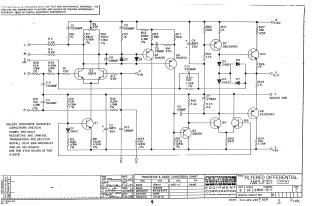
This document provides the schematic diagram for the G590 Filtered Differential Amplifier. It includes details on component values for transistors, diodes, capacitors, and resistors, along with a transistor and diode conversion chart. The document is provided for test and maintenance purposes and remains the property of Digital Equipment Corporation as of 1969.
Related Documents
| Filtered Differential Amplifier Schematic | G590-0-1 |
Site structure and layout ©2026 Majenko Technologies