Resistor Board G626
Order Number: G626-0-1
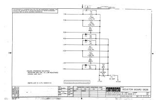
This document is a schematic diagram for the Digital Equipment Corporation Resistor Board G626, dated 1967. It provides the internal circuit layout, featuring resistors (R1 through R8), capacitors (C1 through C4), diodes (D1 through D3), and a fuse (F1). The schematic is intended for test and maintenance purposes and includes a transistor and diode conversion chart.
Related Documents
| Resistor Board G626 | G626-0-1 |
Site structure and layout ©2026 Majenko Technologies