Terminator
Order Number: G715-0-1
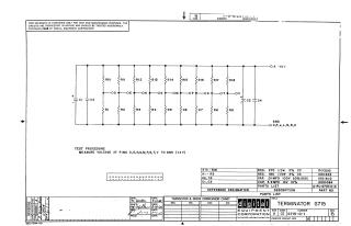
This document contains a schematic diagram for the G715 Terminator module, a component used in Digital Equipment Corporation hardware. The schematic includes a list of parts, including resistors (R1-R18) and capacitors (C1-C4), along with a brief test procedure that instructs the technician to measure the voltage at pins D, E, H, K, M, P, S, T, and V relative to Ground (+4V).
Related Documents
| Terminator | G715-0-1 |
Site structure and layout ©2026 Majenko Technologies