6-4 Input NAND Gates
MI17
Order Number: MI17-0-1
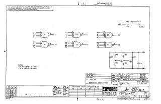
This schematic provides the circuit design for the 6-4 input NAND gates, identified as MI17. The document includes logic gate diagrams, component pin assignments, and a comprehensive parts list detailing the integrated circuits, resistors, and capacitors required for the circuit. It is intended for testing and maintenance purposes.
Site structure and layout ©2026 Majenko Technologies