Rainbow Graphics Card
Order Number: N/A
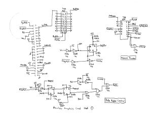
This document contains a detailed series of schematic diagrams for the Rainbow Graphics Card. The schematics cover various functional blocks of the board, including:
- Address Decoding and Data Buffering: Logic for system communication.
- Master Clock and Control Ports: Generation of system timing and I/O control signals.
- Major States and MMU: Logic for managing memory states and memory management unit operations.
- Graphics Display Controller (GDC): Interfacing with the 7220 GDC.
- Video RAM and RAM Control: Logic for managing video memory, including write and output controls.
- Update Buffer: Logic for managing data updates.
- Video Output: Color lookup table (CLUT) addressing, memory, and final analog video output circuitry.
Included is a JEDEC file disassembler for a PAL16L8 chip, providing boolean equations for control logic.
Site structure and layout ©2026 Majenko Technologies